WIRE DIAGRAMS
KG Tour (Karol G) - Scenic LED on Band Risers · SGPS #10883 Task 405
Tape ribbon wiring - one standard
Wire by COLOR. Every ribbon on this rig is terminated to one standard: black, green, red, blue, white = V+, G, R, B, W. Straight through at the tape (color to matching pad); NL8 end below.
NL8 END (wire by color)
| Wire Jacket | Function | NL8 Pin |
|---|---|---|
| BLACK | V+ 24V | 1+ |
| RED | RED | 1- |
| GREEN | GREEN | 2+ |
| BLUE | BLUE | 2- |
| WHITE | WHITE | 3+ |
| - | spare | 3-, 4+, 4- |

LED / TAPE END
Straight through. Jacket order matches the tape pads (black, green, red, blue, white = V+, G, R, B, W). Solder in-line, color to matching pad.
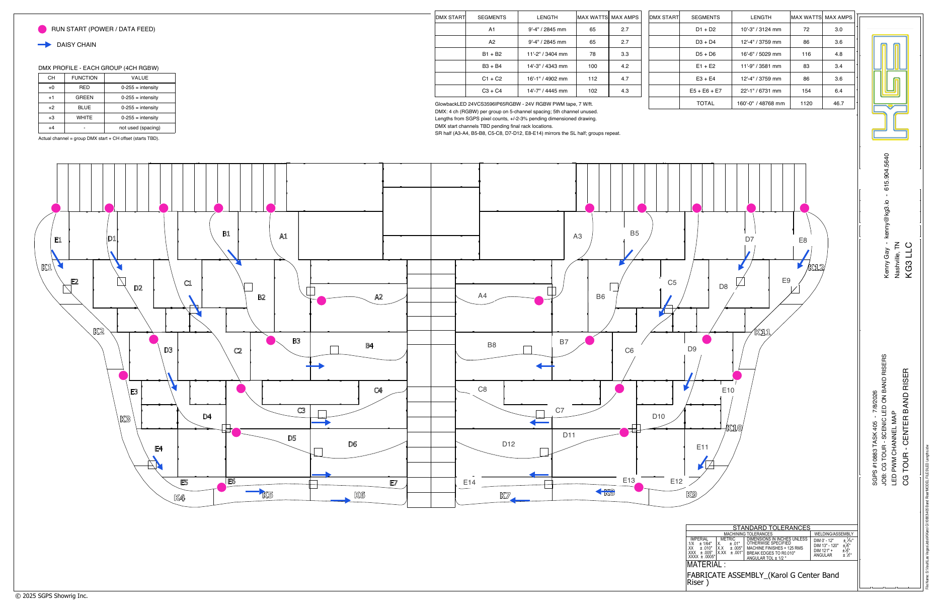
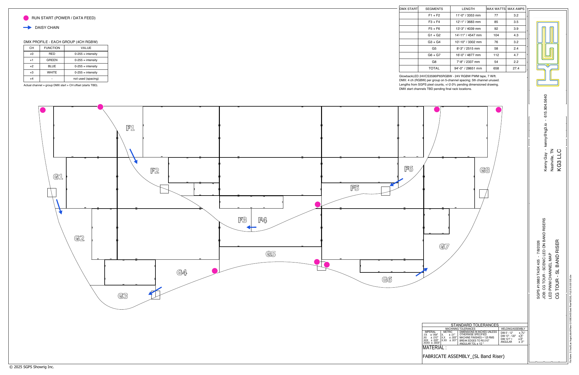
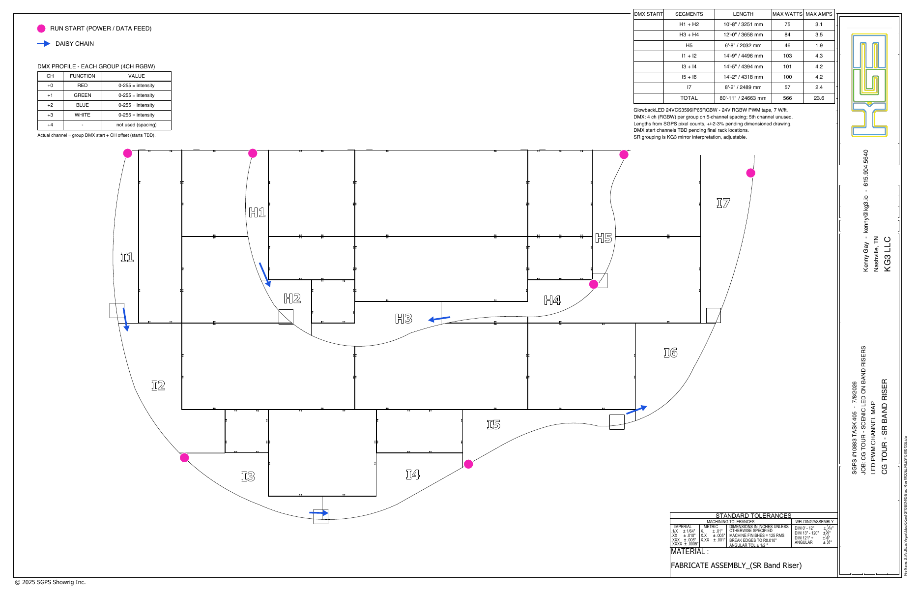
Riser PWM maps
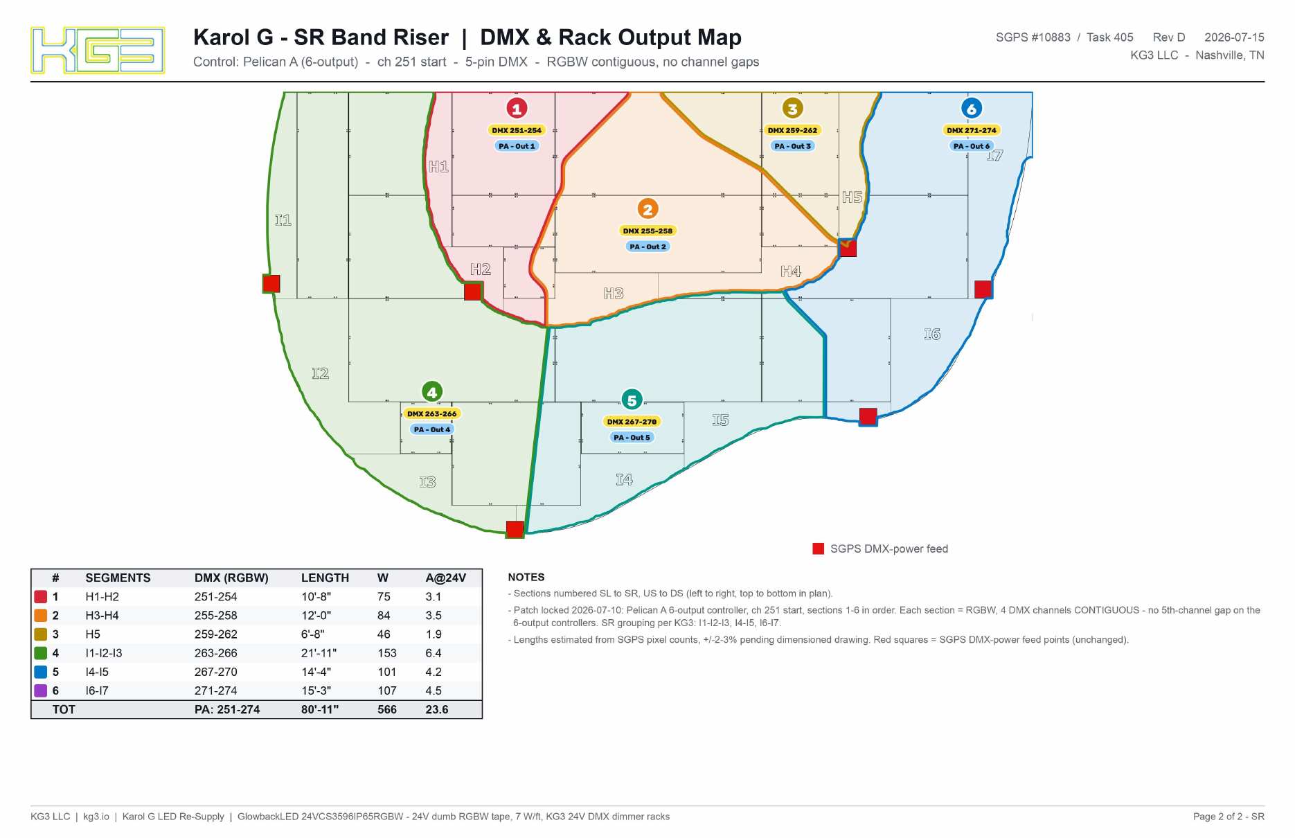
Red square = SGPS DMX-power feed point. Segments daisy-chain within each zone off that feed.
CENTER
STAGE LEFT
STAGE RIGHT
DMX & rack-output maps
Same maps with an added blue pill per zone = the controller output that feeds it (e.g. R1 - Out 13).
CENTER
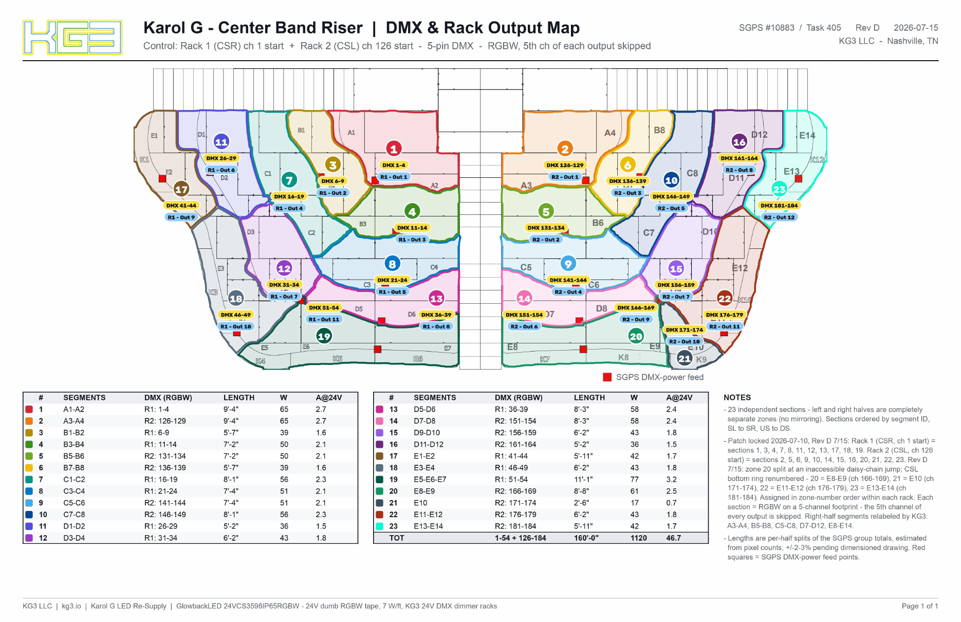
STAGE LEFT
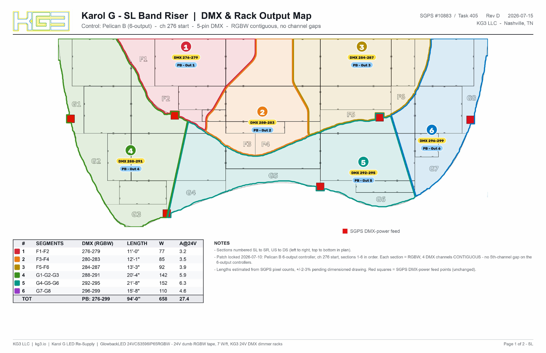
STAGE RIGHT